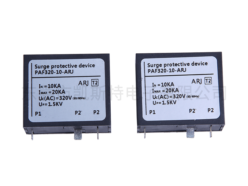
The function of a lightning protection module is to protect various electrical equipment in the power system from damage caused by lightning overvoltage, operation overvoltage, and power frequency transient overvoltage impacts. The main types of lightning protection modules include protection gaps, valve-type lightning arresters and zinc oxide lightning arresters. The protection gap is mainly used to limit atmospheric overvoltage and is generally applied to the protection of incoming line sections in distribution systems, lines and substations. Valve-type lightning arresters and zinc oxide lightning arresters are used for protection in substations and power plants. In systems of 500KV and below, they are mainly used to limit atmospheric overvoltage. In ultra-high voltage systems, they will also be used to limit internal overvoltage or serve as backup protection for internal overvoltage.
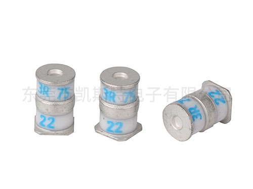
Some gas discharge tubes have glass as the outer shell for the tube. Some use ceramic as the encapsulation shell, and the discharge tube is filled with inert gases with stable electrical performance (such as argon and neon, etc.). The discharge electrodes of commonly used discharge tubes are generally two or three, and the electrodes are separated by inert gases. According to the setting of the number of electrodes, discharge tubes can be classified into two-electrode and three-electrode discharge tubes. The ceramic diode discharge tube is mainly composed of pure iron electrodes, nickel-chromium-cobalt alloy caps, silver-copper welding caps and ceramic tube bodies. The discharge electrodes inside the tube are coated with radioactive oxides, and the inner wall of the tube is also coated with radioactive elements to improve the discharge characteristics.
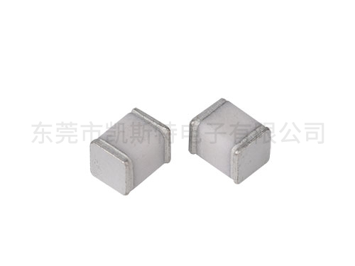
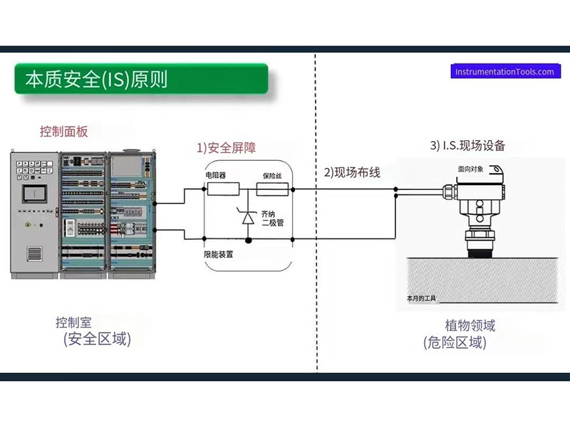
To safely use fuses in hazardous environments, the energy of the spark must be controlled within the fuse to prevent the ignition of explosive substances present in the environment. In intrinsically safe applications, fuses are necessary to help prevent overcurrent conditions and ensure that no sparks sufficient to cause an explosion are generated when the circuit is disconnected. When there is an overcurrent, an arc will be generated inside the fuse when it blows, and this should be confined within the fuse. To provide additional safety guarantees, the fuse will be further encapsulated to ensure that the internal arc does not escape from the fuse and enter the atmosphere.
The term "intrinsic safety" originated from the GB3836.1-2000 standard. Intrinsically safe explosion-proof electrical appliances are one of the classifications of explosion-proof electrical equipment specifically designed for use in underground coal mines. Explosion-proof electrical equipment is generally classified into types such as flameproof type, increased safety type, and intrinsically safe type. The characteristic of intrinsically safe electrical equipment is that all its circuits are intrinsically safe circuits, meaning that the electric sparks and thermal effects generated under normal operation or specified fault conditions cannot ignite the specified explosive mixture. That is to say, this type of electrical appliance does not rely on the explosion-proof casing or filling material, but rather on the energy of the electric spark or thermal effect generated by its circuit during normal use or when a fault occurs being less than 0.28mJ (Class B explosion-proof), that is, the minimum ignition energy when the gas concentration is 8.5% (the most explosive concentration).
The working principle of a discharge tube is gas gap discharge. When a certain voltage is applied between the two poles of the discharge tube, an uneven electric field is generated between the poles. Under the action of this electric field, the gas inside the tube begins to be free. When the applied voltage increases to the extent that the field strength between the electrodes exceeds the insulation strength of the gas, the gap between the two electrodes will be discharged and broken down, changing from the original insulating state to a conductive state. After conduction, the voltage between the two electrodes of the discharge tube is maintained at the residual voltage level determined by the discharge arc path, which is generally very low. This enables electronic devices connected in parallel with the discharge tube to be protected from damage caused by overvoltage.
The Kester electronic safety barrier is a energy-limiting circuit located between the field equipment and the control room equipment. It is used to limit the electrical energy supplied by the control room to the field instruments, ensuring that neither sparks sufficient to ignite dangerous gases nor surface temperatures sufficient to ignite dangerous gases are generated, thereby eliminating the ignition source.
Total16
Total pages:3 |
Current page:1
9The first page
7Previous
Next8
The last page:
Jump